(zk-learning) Building a Graph 3-Coloring R1CS circuit in Circom
Introduction
I just finished the third lecture of the Zero Knowledge Proofs MOOC titled Libraries and Compilers to build ZKP. This lecture featured a tutorial where we learned how to program R1CS circuits with Circom.
In the tutorial we wrote a circuit for proving knowledge of a solution to a Sudoku puzzle, but we didn’t finish the circuit.
In this post I’ll show you the finished circuit and also a brand new circuit for proving knowledge of a graph 3-coloring. In the 3-coloring circuit, we’ll make use of some of the many helpful circuits available in the circomlib repository.
For the rest of this post I’ll assume you have implemented the circuit from the tutorial, or have prior knowledge of Circom. You can find all the code from this post here.
Finishing the Sudoku circuit
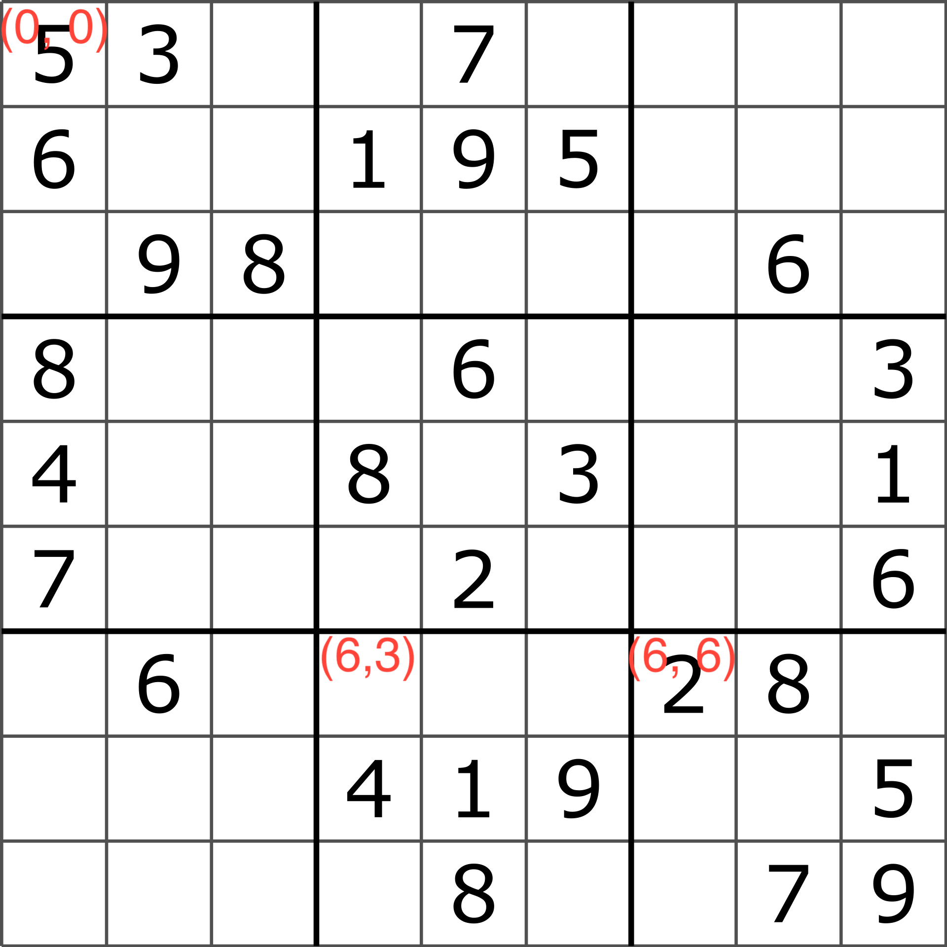
When the tutorial ended we had these constraints on the Sudoku solution:
- Every number in the solution is in the range [1, 9]
- For each row in the solution there are no duplicate numbers
- The solution matches the puzzle for each non-empty number in the puzzle. This one’s important because otherwise we could provide a valid sudoku solution that doesn’t match the input puzzle!
But this is incomplete. Can you come up with an invalid solution that would be accepted by our current circuit?
Answer
Swap the first and last elements of the first row in `sudoku.input.json` and run `make` you'll see.It’s missing two important constraints
- For each column in the solution there are no duplicate numbers
- For each subsquare in the solution there are no duplicate numbers
Let’s tackle each one in turn.
Column uniqueness
We can reuse the Distinct template to check for column uniqueness. Right below the for loop that checks row uniqueness, let’s add a for loop that iterates through the columns to check column uniqueness.
component colIsDistinct[n]; // Constraint that each column in the solution has no duplicates
for (var col = 0; col < n; col++) {
    colIsDistinct[col] = Distinct(n);
    for (var row = 0; row < n; row++) {
        // Column duplicate check
        colIsDistinct[col].in[row] <== solution[row][col];
    }
}
That one was pretty straightforward!
Subsquare uniqueness
One of the Sudoku rules is that the numbers in each “subsquare” must be unique. A 9x9 puzzle has nine 3x3 subsquares. Each of these 3x3 subsquares must have unique numbers.
To solve this I defined a template called DinstinctSubsquare that takes a row offset and column
offset as input. The row offset and column offset are used to determine which subsquare of the
solution to check, and then it feeds those numbers into the Dinstinct template:
template DistinctSubsquare(sqrtN, rowOffset, colOffset) {
    var n = sqrtN * sqrtN;
    signal input solution[n][n];
    component distinct = Distinct(n);
    var i = 0;
    for (var row = sqrtN * rowOffset; row < sqrtN * rowOffset + sqrtN; row++) {
        for (var col = sqrtN * colOffset; col < sqrtN * colOffset + sqrtN; col++) {
            distinct.in[i] <== solution[row][col];
            i = i + 1;
        }
    }
}
The rowOffset and colOffset are combined with the square root of n to map the
subsquare’s coordinates to the solution’s coordinates. For example, if we assume that the
top left number in the solution is at coordinate (0, 0), then the top left element
in the subsquare at the top left (rowOffset = 0, colOffset = 0) is at coordinate (rowOffset * 3, colOffset * 3) = (0, 0), and the top left element
in the subsquare at the bottom right (rowOffset = 2, colOffset = 2) is at coordinate (rowOffset * 3, colOffset * 3) = (6, 6)
In the main template we iterate over the nine possible row and coloumn offset pairs and enforce the uniqueness constraint on each one.
// Verify the subsquares
var sqrtN = 0;
while (sqrtN * sqrtN < n) {
    sqrtN = sqrtN + 1;
}
component distinctSubsquares[n];
var subsquareIndex = 0;
for (var rowOffset = 0; rowOffset < sqrtN; rowOffset++) {
    for (var colOffset = 0; colOffset < sqrtN; colOffset++) {
        distinctSubsquares[subsquareIndex] = DistinctSubsquare(sqrtN, rowOffset, colOffset);
        distinctSubsquares[subsquareIndex].solution <== solution;
        subsquareIndex = subsquareIndex + 1;
    }
}
Something to note here is that I calculate sqrtN in code. Alternatively we could have passed
it in as a template argument.
And that’s all we need! The Sudoku circuit is complete.
A Circuit for Graph 3-Colorings
I decided to put my skills to the test by writing a circuit to prove knowledge of a graph 3-coloring. The idea is the verifier sees a graph without colors, and the prover wants to convince the verifier that it knows a way to color the graph with just 3 colors such that no two nodes that share an edge have the same color. Here is a valid 3-coloring for a graph with 10 nodes.
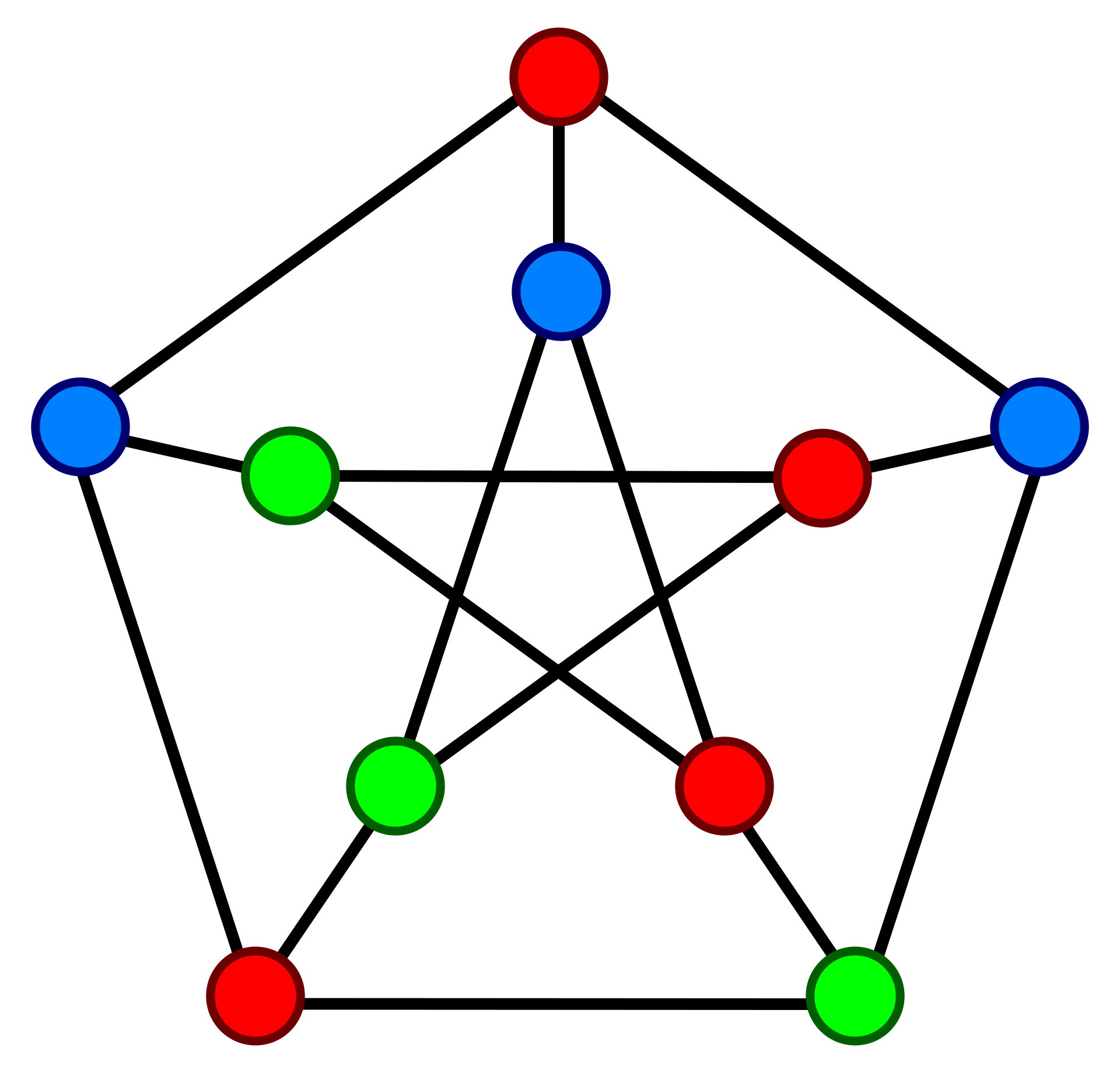
Given a minute or two you could come up with this coloring yourself. But the general problem is NP-Complete, meaning there is no known efficient algorithm to find a coloring.
Let’s dive in.
Setup
Before we start writing the circuit we need to make modifications to the repo so we can build and test it.
Modifying the makefile to support multiple circuits
The first modification is to add support for different circuit names in the Makefile.
From the lecture tutorial, the Makefile is hardcoded to run on sudoku.circom. By adding a circuit parameter we can quickly swap out the name of the circuit we want to compile and test.
The Makefile went from this
SHELL = zsh

circom = sudoku.circom
r1cs = sudoku.r1cs
wasm = sudoku_js/sudoku.wasm
...
to this
SHELL = zsh

circuit = threecoloring # NEW!
circom = $(circuit).circom
r1cs = $(circuit).r1cs
wasm = $(circuit)_js/$(circuit).wasm
...
So now we can run whole compilation + proof gen + verification pipeline
for the circuit of our choice. In this case I set the circuit name to threecoloring,
which means our circuit file is threecoloring.circom and our input file is threecoloring.input.json
Choosing the input format
The next thing I did was define the format for threecoloring.input.json. I represented the edges as a 2-D array edges parameter. If edges[i][j] = 1 then there’s an edge connecting
nodes i and j. If edges[i][j] = 0, then i and j don’t share an edge.
I represented the coloring as a 1-D array colors parameter, where colors[i] is the color of
i. The valid colors are 1 = RED, 2 = BLUE, and 3 = GREEN. Recall that colors is a
PRIVATE INPUT that only the prover sees.
Here’s our colored graph with the numbered nodes and colors:
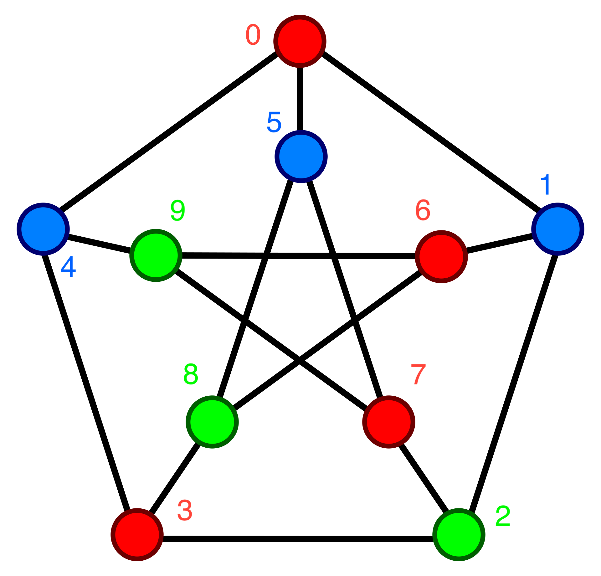
And here’s that same graph encoded in threecoloring.input.json.
{
    "edges": [
        ["0", "1", "0", "0", "1", "1", "0", "0", "0", "0"],
        ["1", "0", "1", "0", "0", "0", "1", "0", "0", "0"],
        ["0", "1", "0", "1", "0", "0", "0", "1", "0", "0"],
        ["0", "0", "1", "0", "1", "0", "0", "0", "1", "0"],
        ["1", "0", "0", "1", "0", "0", "0", "0", "0", "1"],
        ["1", "0", "0", "0", "0", "0", "0", "1", "1", "0"],
        ["0", "1", "0", "0", "0", "0", "0", "0", "1", "1"],
        ["0", "0", "1", "0", "0", "1", "0", "0", "0", "1"],
        ["0", "0", "0", "1", "0", "1", "1", "0", "0", "0"],
        ["0", "0", "0", "0", "1", "0", "1", "1", "0", "0"]
    ],
    "colors": [
        "1",
        "2",
        "3",
        "1",
        "2",
        "2",
        "1",
        "1",
        "3",
        "3"
    ]
}
Now that we’ve finished the setup, we can get started on the circuit.
Writing the circuit
Let’s start by defining our base template and the main function. We’ll have the edges and colors input signals,
but only edges will be public
template ThreeColoring(n) {
    signal input edges[n][n];
    signal input colors[n];

    // TODO - implement me
}

component main {public[edges]} = ThreeColoring(10);
What constraints do we need?
- Each color must be a valid color in the range [1,3]
- Each node must have a different color from all of its neighbors
Constraining each color to a valid color
To implement this constraint I drew inspiration from the
Bits4 and OneToNine templates in the Sudoku circuit.
For this circuit we need a OneToThree.
// Enforce 0 <= in < 4
template Bits2() {
    signal input in;
    signal bits[2];
    var bitsum = 0;
    for (var i = 0; i < 2; i++) {
        bits[i] <-- (in >> i) & 1;
        bits[i] * (bits[i] - 1) === 0;
        bitsum = bitsum + 2 ** i * bits[i];
    }
    bitsum === in;
}

template OnetoThree() {
    signal input in;
    component lowerBound = Bits2();
    component upperBound = Bits2();
    // lowerBound checks 0 <= (in - 1) < 4 ==> 1 <= in < 5
    // upperBound checks 0 <= in < 4
    // combining those constraints we get 1 <= in < 4 ==> 1 <= in <= 3, as desired
    lowerBound.in <== in - 1;
    upperBound.in <== in;
}
Now we can enforce OneToThree on each color in the main template
template ThreeColoring(n) {
    signal input edges[n][n];
    signal input colors[n];

    // Ensure all colors are in set {1, 2, 3}
    component inRange[n];
    for (var node = 0; node < n; node++) {
        inRange[node] = OnetoThree();
        inRange[node].in <== colors[node];
    }

    // TODO
}

component main {public[edges]} = ThreeColoring(10);
Constraining each neighbor to have different colors
This is the more interesting constraint, and the one that really emphasizes the HDL (Hardware Description Language) nature of Circom. HDL’s are fundamentally different from PL’s (Programming Languages), and we’ll see that difference in a second.
Here’s how I naively tried to implement the dinstinct-neighbor-colors constraint:
// Ensure the colors of a node's neighbors don't match the node's color
component checkNeighbor[n][n];
for (var node = 0; node < n; node++) {
    for (var neighbor = 0; neighbor < n; neighbor++) {
        if (edges[node][neighbor] == 1) {
            checkNeighbor[node][neighbor] = NonEqual(); // NonEqual same as in sudoku.circom
            checkNeighbor[node][neighbor].in0 <== colors[node];
            checkNeighbor[node][neighbor].in1 <== colors[neighbor];
        }
    }
}
But the compiler produces an error!
circom threecoloring.circom --r1cs --wasm
error[T2005]: Typing error found
    ┌─ "threecoloring.circom":100:17
    │
100 │             if (edges[node][neighbor] == 1) {
    │                 ^^^^^^^^^^^^^^^^^^^^^^^^^^ There are constraints depending on the value of the condition and it can be unknown during the constraint generation phase

previous errors were found
make: *** [threecoloring_js/threecoloring.wasm] Error 1
What does this error mean? The Unknowns section Circom’s documentation gives us an answer.

The problem is edges[node][neighbor] is an input signal, which means it’s unknown at compile
time. This would result in a non-linear, non-quadratic constraint during the constraint generation
phase, and that’s not allowed. I read the Constraint Generation documentation but it doesn’t give details on why this isn’t disallowed.
Presumably it has to do with prover efficiency.
So how do we work around this? It took some time, but here was my idea. We’re going to compare each pair of nodes (whether they’re neighbors or not) and do the following
- Generate a bit
xthat’s1if two nodes have the same color,0otherwise - Generate a bit
ythat’s1if the two nodes are neighbors,0otherwise - Multiply those two bits together to get
z = x * y. Ifz == 0then the constraint that two neighbor’s colors are different is satisfied.
Does it actualyl work? Let’s enumerate the cases…
- When the nodes aren’t neighbors
- Then
y = 0andz = x*y = x*0 = 0. The constraint is satisfied no matter the value ofx. Great! We don’t care about nodes who are NOT neighbors.
- Then
- When the nodes are neighbors and the colors are the same
- Then
y = 1andx = 1, andz = x*y = 1*1 = 1. The constraint isn’t satisfied. Great! We want to reject colorings where neighbors have the same color.
- Then
- When the nodes are neighbors and the colors are not the same
- Then
y = 1andx = 0, andz = x*y = 0*1 = 0. The constraint is satisfied. Great! The neighbors have different colors, so this is potentially a valid coloring.
- Then
Cool, the design works. How do we implement it in the circuit?
Generating bit y is easy, because that’s just edges[node][neighbor]. How do
we generate bit x? Luckily there’s a IsEqual template available in the circomlib repository.
If the two input signals are equal, then the ouput signal is 1. Otherwise the output signal is 0.
// Taken from https://github.com/iden3/circomlib/blob/master/circuits/comparators.circom
template IsZero() {
    signal input in;
    signal output out;

    signal inv;

    inv <-- in!=0 ? 1/in : 0;

    out <== -in*inv +1;
    in*out === 0;
}

// Taken from https://github.com/iden3/circomlib/blob/master/circuits/comparators.circom
template IsEqual() {
    signal input in[2];
    signal output out;

    component isz = IsZero();

    in[1] - in[0] ==> isz.in;

    isz.out ==> out;
}
Now we can define the template CheckNodePair to implement the procedure I described above
template CheckNodePair() {
    signal input color1;
    signal input color2;
    signal input areNeighbors; // y bit

    component isEqual = IsEqual();
    isEqual.in[0] <== color1;
    isEqual.in[1] <== color2;

    // isEqual.out is the x bit
    isEqual.out * areNeighbors === 0;
}
With CheckNodePair implemented, we can update our naive for loop
// Ensure the colors of a node's neighbors don't match the node's color
component checkNeighbor[n][n];
for (var node = 0; node < n; node++) {
    for (var neighbor = 0; neighbor < n; neighbor++) {
        checkNeighbor[node][neighbor] = CheckNodePair();
        checkNeighbor[node][neighbor].color1 <== colors[node];
        checkNeighbor[node][neighbor].color2 <== colors[neighbor];
        checkNeighbor[node][neighbor].areNeighbors <== edges[node][neighbor];
    }
}
And now we’ve implemented all of the constraints. You can try running make and verify that
the pipeline runs to completion :).
Conclusion
The limitations of using an HDL
Finishing the Sudoku circuit was straightforward, but we saw in the 3-Coloring circuit how we had to cleverly work around the limitations of Circom. Not being able to use basic PL primitives like if statements is one of the big drawbacks of using an HDL. As we progress through the course I imagine we’ll learn to work with libraries at a higher abstraction level. That said, it’s good to understand what’s going on under the hood. Plus, manually wiring up the circuits can be fun ;).
Moving away from toy examples
Althought more complex than the Sudoku circuit, the 3-Coloring circuit is still just a pedagogical exercise. I’m really curious to see who’s using Circom in production applications, and to what level of sophistication in applications is possible. I would guess that iden3 (the company who built Circom) is using it. Are there others?